In order to implement the principles of circularity in the design of the product, the Plug-N-Harvest Façade Modular Kit, Eco Intelligent Growth, a circular economy advisory and innovation company, has developed a tool: a circular economy design guideline based on the following five Circular Economy Design Requirements (CDR). The implementation of the CDRs across all Plug-N-Harvest Work Packages is the road to arrive to a circular business model:
- CDR 1: Use safe materials
- CDR 2: Think in System circularity
- CDR 2.1: Define the right cycle
- CDR 2.2: Make it easy to disassemble
- CDR 2.3: Enhance materials productivity
- CDR 2.4: Choose the inner cycle
- CDR 3: Preserve transparency and traceability
- CDR 4: Keep track of valuable materials
- CDR 5: Rethink business model / New Partnership models / implement business models that support a circular transition.
For each Circular Design Requirement defined the following characteristics are examined:
- Methodology: used to assess and meet the intention defined in each CDR
- Tools: available to implement the CDR
- Key Objectives (KO), Key Performance Indicators (KPI) and (DPI) of Plug n Harvest project directly or indirectly related with this CDR
- Strategies defined to implement each CDR
- Relevant case studies. Examples and iconic case studies to exemplify the implementation of each CDR, and example of how the CDR has been implemented in Plug-N-Harvest project.
CDR 1: Use safe materials
Circular economy is based in the use of nontoxic materials to provide a healthy environment now and in the future. Design with materials that are safe for humans & the environment in the applications in which they are used:
- Safe during extraction and manufacturing,
- Use phase (intentional & likely unintentional),
- Cycling phase such as reuse, remanufacturing, recycling, composting, etcetera.
- Unintentional but probable end uses such as landfilling, incineration, etcetera.
The goal is for all materials of the Plug-N-Harvest system to be manufactured using only those materials that are optimal and do not contain any toxic or unknown materials.
CDR 2: Think in System circularity
In nature, there is no concept of waste. Everything is effectively food for another organism or system. Materials are reutilized in safe cycles. The Circular Economy aims to work on the same principles as Nature.
However, products and artefacts are not always compatible with the biological cycle and can’t be safely returned to nature. Many materials such as plastics, composites, minerals or even paper, once processed and mixed to make products, might become harmful both for humans and environment, in addition to not being biodegradable. Thus, they are converted into wastes and can potentially become a global problem.
Besides, many of these materials come from limited resources (virgin and non-renewable), leading to the depletion of available and valuable resources.
Both first and second dimensions as described in this CDR, have to be considered to enable the industrial development at the required pace, without compromising the future availability of materials and the unintended consequences for living beings. This means that biodegradable and non-biodegradable materials are to be circularity sourced and properly cycled.
To align the ADBE System design with Circular Economy business model, it is necessary to eliminate the concept of “waste”, and converting all the potential waste into nutrients.
To achieve this goal is necessary to consider the 3 dimensions of products and materials:
- Source for circularity: select recycled/ rapidly renewable materials
- Design for circularity: select reciclable materials
- Systems circularity: Plan materials recovery. Material Passports, take-back programs
The methodology followed to optimize the Material Reutilization and Product circularity of ADBE System is the Cradle to Cradle CertifiedTM Products Program version 4. The new version considers the following dimensions, shown in figure, and aligned with the Scope of CDR 4:
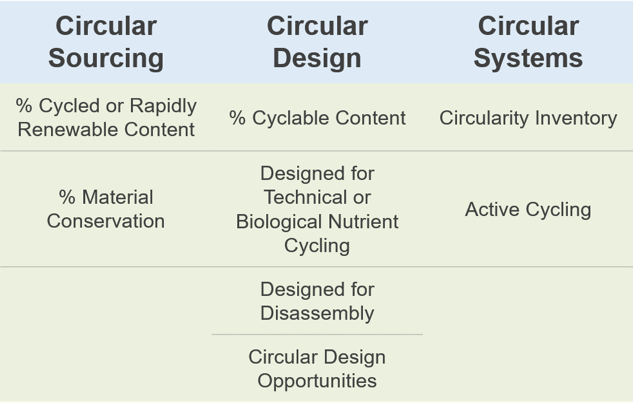
To promote and enable Circular business models, CDR 4 has been broken down in the following 4 design steps:
CDR 2.1: Define the right cycle
The Circular Economy, based on the Cradle to Cradle® principles, distinguishes to different cycles: the Biological Cycle and the Technical Cycle
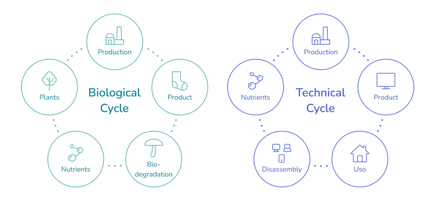
All products present in a Circular System need to be identified as Biological Nutrient (BN) or as a Technical Nutrient (TN). Biological nutrients have been designed to flow though biological cycled and be safely reintroduced into nature. Otherwise, TN are mainly non-renewable materials designed to be cycled by industry.
CDR 2.2: Make it easy to disassemble
The aim is to design ADBE to enable the disassembly of the system into separate materials, to make each of them recyclable through the adequate path. In the design process always keep in mind deconstruction after use, which will influence in how to construct. Design ADBE to enable the disassembly of the system into separate materials, to make each of them recyclable through the adequate path.
According to Circular Economy principles, buildings are material banks for the future. Thus, design for deconstruction should enable to recover materials separately to return each to the corresponding material cycle, for its infinite reuse, recovering in this manner the value of each material, which in several cases will be higher over time (i.e. copper).
If materials are joined and mixed together the quality of the recycled output is in general lower than the input (downcycling). In this case, material’s residual value is drastically reduced and its future potential applications are limited – often to a sole new cycle, creating restrictions to the business model, with associated costs (i.e. for new waste management).
In contrast, designing from a System Circularity perspective, products are prepared to be disassembled: every component and subcomponent can be recovered separately to enable its upcycling.
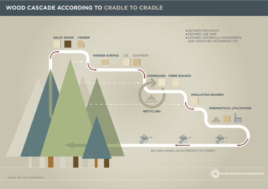
CDR 2.3: Enhance materials productivity
Cascading keeps materials in circulation for longer. Thinks in life extension through maintenance, repair, parts and components recycling for other possible ways to enhance its productivity.
CDR 2.4: Choose the inner cycle:
The power of the inner circle refers to minimizing comparative materials use vis-à-vis the linear production system. The tighter the circle, i.e. the less a product has to be changed in reuse, refurbishment and remanufacturing and the faster it returns to use, the higher the potential savings on the shares of material, labour, energy and capital still embedded in the product, and the associated externalities (such as greenhouse gas (GHG) emissions, water and toxicity).
CDR 3: Preserve transparency and traceability
In general waste are “Materials without Identity” (Madaster, 2018). Correct identification and characterization of materials is a critical step to convert Wastes into Nutrients, which can be perpetually cycled in a safe way. Furthermore, this information needs to go through different actor along the supply chain. Transparency between different stakeholders as well as traceability along the materials flows are key elements, to effectively cycle the materials within an economy, and jump form a linear model into a circular model.
CDR 4: Keep track of valuable materials
Many resources are forecasted to run out within a relatively short period, other are subject to risk of supply disruption or serve for a purpose deemed important. Mineral criticality is a subjective concept that has evolved throughout history (Hayes et al, 2018). An abundance of literature has been published over the last decade, encompassing a variety of criteria and methodologies to define critical raw materials.
The approach of this Requirement to identify which materials are considered Critical is aligned with Critical Raw Materials (CRMs) defined by European Commission.
CDR 5: Rethink business model / New Partnership models / implement business models that support a circular transition.
The Circular Economy requires the development of new relationships between stakeholders in order to create and grow circular models.
The implementation of a new economy requires the development of new business models and to redefine relationships among all the stakeholders involved in building process.
Relation among users, building contractor, product manufacturer and materials suppliers change drastically, they go from a linear, static relationship (stakeholders are either suppliers, manufacturers of goods, or users/clients, etc.) towards an ‘ecosystemic’ scenario, in which stakeholders play different roles, and require new partners to create and grow circular models. In general, the relation is two or multiple-way, and all stakeholders become partners and co-responsible for product circularity.
This circular economy design guideline has been reflected in a tool that is openly available on the website. On this page there are the complete guideline and the details of each characteristic for each one of the five Circular Economy Design Requirements (CDR)